dienelectrics@gmail.com
 0909186879 dienelectrics@gmail.com


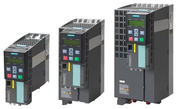
Whether installed in the intake and exhaust fans of air-conditioning systems, in pumps for heating and cooling circuits, or in compressors for refrigeration units: SINAMICS G120P converters are ideally suited to meet every requirement of building management systems.
Stay flexible: Due to their IP20 and IP55 degrees of protection, the PM230 Power Modules can not only be installed in the control cabinet, but can also be directly at the machine. And thanks to different EMC filters, they can be used both in the public power grid and in industrial networks.
A well-thought-out portfolio: Apart from standard functions such as setpoint specifications, on/off switching logic, protection and monitoring of machine, motor and converter, SINAMICS G120P also offers numerous industry-specific functions. These include the regulation of two or multiple zones and one fire protection mode which ensures the longest possible operation in an emergency.
- Full control – Real-time clock with exact time stamp for error and warning logging, max. buffer time five days, automatic summer / winter changeover
- Freely programmable – Digital timers for the control of three selectable events depending on the weekday / hour / minute
|
SINAMICS G120P in the Building Technologies: |
|
|---|---|
|
Power: |
0,37 - 90 kW |
|
Voltage: |
3 AC 380 - 480 V |
|
Control procedure: |
U/f control with stator flux orientation, vector control without encoder |
Growing complexity of plants and globalization of markets: The drives of the SINAMICS G120P series always have the right answer for the special features of the process industry.
Usable and available worldwide – SINAMICS G120P is ready to meet your global requirements. And with the key functions of speed control, controlling range, efficiency and communication level, it ensures simple operation.
Thanks to the upgraded PM330 Power Modules, you now have a complete series of SINAMICS G120P products at your disposal: in all sizes and across all voltage ranges, from 400 V to 690 V. A flexibly applicable and consistent approach, which minimizes your configuration and implementation overheads.
The new PM240P-2 Power Modules increases your process reliability: with integrated safety functionality up to the SIL3 level.
- Process reliability – Utmost safety level thanks to Integrated safety functions, safe electronic switch-off (Safe Torque-off / Safe Stop 1)
- Robustness – Even for special operating conditions such as temperatures ranging from -10° C to 60° C and aggressive environments (resistance to pollutants)
- Cost saving – Increased energy efficiency with higher output voltage (98 %) through integrated dc link reactor
- Enhanced flexibility – due to the new voltage level up to 690 V
- Saving space – allows compact control cabinets
- Robustness – through numerous functions such as output voltage sensing
- Total integration – the complete product series is available
|
SINAMICS G120P in the Process industry |
|
|---|---|
|
Power: |
11 - 630 kW |
|
Voltage: |
3 AC 380 - 480 V and 3 AC 500 - 690 V |
|
Control procedure: |
U/f control with stator flux orientation, vector control without encoder |

Power Modules for industrial applications and building technology

Control Units have been especially designed for pump, fan, compressor applications

Supplementary system components for SINAMICS G120P
The Control Unit controls and monitors the Power Module and the connected motor in several selectable operating modes. It supports the vertical integration in Totally Integrated Automation (TIA) through the communication options PROFINET and PROFIBUS via a high level controller or monitoring device.
The specific control unit (CU230P-2) is ideal for the use with drives with integrated technology functions for pump, fan and compressor applications. The I/O interface, the fieldbus interfaces and the additional software functions optimally support these applications.
|
CU230P-2 ... |
HVAC |
DP |
PN |
|---|---|---|---|
|
Digital inputs |
6 |
6 |
6 |
|
Digital outputs |
3 |
3 |
3 |
|
Analog inputs |
4 |
4 |
4 |
|
Analog outputs |
2 |
2 |
2 |
|
MMC/SD card Slot |
Yes |
Yes |
Yes |
|
Motor temperature sensors |
PTC/KTY |
PTC/KTY |
PTC/KTY |
|
Communication |
RS485/USS, |
PROFIBUS |
PROFINET |
|
Profiles |
- |
PROFIdrive |
PROFIdrive |


Example: CU230P‑2 Control Unit with open and closed terminal covers
|
Terminal No. |
Signal |
Features |
|---|---|---|
|
Digital inputs (DI) – Standard |
||
|
69 |
DI COM |
Reference potential for digital inputs |
|
5 ... 8, |
DI0 … DI5 |
Freely programmable |
|
Digital outputs (DO) |
||
|
18 |
DO0, NC |
Relay output 1 |
|
19 |
DO0, NO |
Relay output 1 |
|
20 |
DO0, COM |
Relay output 1 |
|
21 |
DO1, NO |
Relay output 2 |
|
22 |
DO1, COM |
Relay output 2 |
|
23 |
DO2, NC |
Relay output 3 |
|
24 |
DO2, NO |
Relay output 3 |
|
25 |
DO2, COM |
Relay output 3 |
|
Analog inputs (AI) |
||
|
3 |
AI0+ |
Differential input, switchable between current and voltage |
|
4 |
AI0- |
|
|
10 |
AI1+ |
Differential input, switchable between current and voltage |
|
11 |
AI1- |
|
|
50 |
AI2+ |
Non-isolated input, switchable between current and temperature sensors, type Pt1000/LG‑Ni1000/DIN‑Ni1000 |
|
51 |
GND |
Reference potential of the AI2/internal electronics ground |
|
52 |
AI3+ |
Non-isolated input for temperature sensors, type Pt1000/LG‑Ni1000/DIN‑Ni1000 |
|
53 |
GND |
Reference potential of the AI3/internal electronics ground |
|
Analog outputs (AO) |
||
|
12 |
AO0+ |
Non-isolated output |
|
13 |
GND |
Reference potential of the AO0/internal electronics ground |
|
26 |
AO1+ |
Non-isolated output |
|
27 |
GND |
Reference potential of the AO1/internal electronics ground |
|
Motor temperature sensor interface |
||
|
14 |
T1 MOTOR |
Positive input for motor temperature sensor |
|
15 |
T2 MOTOR |
Negative input for motor temperature sensor |
|
Power supply |
||
|
9 |
+24 V OUT |
Power supply output |
|
28 |
GND |
Reference potential of the power supply/internal electronics ground |
|
1 |
+10 V OUT |
Power supply output |
|
2 |
GND |
Reference potential of the power supply/internal electronics ground |
|
31 |
+24 V IN |
Power supply input |
|
32 |
GND IN |
Reference potential of the power supply input |
|
35 |
+10 V OUT |
Power supply output |
|
36 |
GND |
Reference potential of the power supply/internal electronics ground |
1) The following applies to systems complying with UL: A maximum of 3 A, 30 V DC or 2 A, 250 V AC may be connected via terminals 18 / 20 (DO0 NC) and 23 / 25 (DO2 NC).
Below is a list of functions sorted according to the following categories:

Connection diagram for the CU230P‑2 Control Unit series
More information about the interfaces of the Control Unit is available on the Internet at
https://support.industry.siemens.com/cs/document/109477360

Communication interface USS, Modbus RTU, BACnet MS/TP, FLN P1 for CU230P‑2 HVAC

PROFIBUS DP communication interface

PROFINET communication interface, EtherNet/IP
|
Control Unit |
CU230P‑2 HVAC |
CU230P‑2 DP |
CU230P‑2 PN |
|---|---|---|---|
|
|
6SL3243-0BB30-1HA3 |
6SL3243-0BB30-1PA3 |
6SL3243-0BB30-1FA0 |
|
Electrical specifications |
|||
|
Operating voltage |
24 V DC via the Power Module or by connecting to an external 20.4 ... 28.8 V DC power supply |
||
|
Current consumption, max. |
0.5 A |
||
|
Protective insulation |
PELV according to EN 50178 |
||
|
Power loss, max. |
5 W |
||
|
Interfaces |
|||
|
Digital inputs – Standard |
6 isolated inputs, optically isolated; NPN/PNP logic can be selected using the wiring |
||
|
11 V |
||
|
5 V |
||
|
5.5 mA |
||
|
Digital outputs |
3 relays |
||
|
250 V AC, 2 A (inductive load) |
||
|
30 V DC, 0.5 A (ohmic load) |
||
|
Analog inputs |
Analog inputs are protected against inputs in a voltage range of ± 30 V and have a common-mode voltage in the ± 15 V range |
||
|
Switchable with DIP switch between voltage and current: These differential inputs can be configured as additional digital inputs. |
||
|
Switchable with DIP switch between 0/4 ... 20 mA current and temperature sensors, type Pt1000/LG‑Ni1000/DIN‑Ni1000, |
||
|
Temperature sensors, type Pt1000/LG‑Ni1000/DIN‑Ni1000, |
||
|
Analog outputs |
The analog outputs have short-circuit protection |
||
|
Switchable between voltage and current using parameter setting: Voltage mode: 10 V, min. burden 10 kΩ |
||
|
PTC/KTY interface |
1 motor temperature sensor input, |
||
|
Bus interface |
|||
|
Fieldbus protocols |
|
|
|
|
Profile |
– |
|
|
|
Hardware |
Plug-in terminal, insulated, |
9-pin SUB-D socket, insulated, |
2 × RJ45, PROFIdrive profile V4.1, device name can be stored on the device Max. 100 Mbit/s (full duplex) |
|
Control Unit |
CU230P‑2 HVAC |
CU230P‑2 DP |
CU230P‑2 PN |
|---|---|---|---|
|
|
6SL3243-0BB30-1HA3 |
6SL3243-0BB30-1PA3 |
6SL3243-0BB30-1FA0 |
|
Tool interfaces |
|||
|
Memory card |
SINAMICS SD card |
||
|
Operator panels |
|
||
|
Can be directly plugged on |
||
|
Can be directly plugged on |
||
|
Required when no operator panel is plugged in order to achieve degree of protection IP55 on PM230 Power Modules degree of protection IP55/UL Type 12 |
||
|
PC interface |
USB (connection via PC inverter connection kit 2) |
||
|
Open-loop/closed-loop control techniques |
|||
|
U/f linear/quadratic/parameterizable |
✓ |
||
|
U/f with flux current control (FCC) |
✓ |
||
|
U/f ECO; linear/quadratic |
✓ |
||
|
Vector control, sensorless |
✓ |
||
|
Software functions |
|||
|
Setpoint input |
✓ |
||
|
Fixed frequencies |
16, parameterizable |
||
|
JOG |
✓ |
||
|
Digital motorized potentiometer (MOP) |
✓ |
||
|
Ramp smoothing |
✓ |
||
|
Extended ramp-function generator (with ramp smoothing OFF3) |
✓ |
||
|
Slip compensation |
✓ |
||
|
Signal interconnection with BICO technology |
✓ |
||
|
Free function blocks (FFB) for logical and arithmetic operations |
✓ |
||
|
Switchable drive data sets (DDS) |
✓ (4) |
||
|
Switchable command data sets (CDS) |
✓ (4) |
||
|
Flying restart |
✓ |
||
|
Automatic restart after line supply failure or operating fault (AR) |
✓ |
||
|
Technology controller (internal PID) |
✓ |
||
|
Hibernation mode with internal/external PID controller |
✓ |
||
|
Belt monitoring with and without sensor (load torque monitoring) |
✓ |
||
|
Dry-running/overload protection monitoring (load torque monitoring) |
✓ |
||
|
Thermal motor protection |
✓ (I2t, sensor: PTC/Pt1000/KTY/bimetal) |
||
|
Thermal inverter protection |
✓ |
||
|
Motor identification |
✓ |
||
|
Auto-ramping (Vdcmax controller) |
✓ |
||
|
Kinetic buffering (Vdcmin controller) |
✓ |
||
|
Possible braking functions |
|
||
|
Control Unit |
CU230P‑2 HVAC |
CU230P‑2 DP |
CU230P‑2 PN |
|---|---|---|---|
|
|
6SL3243-0BB30-1HA3 |
6SL3243-0BB30-1PA3 |
6SL3243-0BB30-1FA0 |
|
Mechanical specifications and ambient conditions |
|||
|
Degree of protection |
IP20 |
||
|
Signal cable cross-section |
0.15 ... 1.5 mm2 (AWG28 ... AWG16) |
||
|
Operating temperature |
For CU230P‑2 HVAC/DP: -10 ... 60 °C (14 ... 140 °F) For CU230P‑2 PN:-10 ... 55 °C (14 ... 131 °F) With IOP/BOP‑2: 0 ... 50 °C (32 ... 122 °F) Derating of 3 K/1000 m applies to Control Units as of an installation altitude of 1000 m (3281 ft) above sea level. |
||
|
Storage temperature |
-40 ... +70 °C (-40 ... +158 °F) |
||
|
Relative humidity |
<95 %, condensation not permissible |
||
|
Dimensions |
|
||
|
73 mm (2.87 in) |
||
|
199 mm (7.83 in) |
||
|
65.5 mm (2.58 in) |
||
|
Weight, approx. |
0.61 kg (1.34 lb) |
||